.png)
Cyclone Calculation
Cyclone is a commonly used equipment that separates the solid particles from gas flow. Standard cyclone design consists of flow entry that creates vortex, axial clean gas outlet and dust discharge opening. Performance of cyclone can be determined via its dust collecting efficiency and pressure drop. Design criteria of cyclone can be high efficiency or high capacity.


Parameter
Flow Rate
Particle Density
Inlet Velocity
Value
Unit
Particle Quantity with Different Particle Diameters:
m³/h
Particle Diameter
Percentage (%)
kg/m³
m/s
##
##
Cyclone Diameter
Inlet Height
m
m
##
##
Inlet Width
Vortex Length
m
m
##
##
Vortex Diameter
Cyclone Straight Length
m
m
##
##
Cyclone Conical Length
m
Cyclone Total Length
m
##
##
Outlet Diameter
m
Air Density
kg/m³
Air Viscosity
m²/s
Results:
Pressure Drop in Heads (Unitless)
##
Number of Revolutions (Unitless)
##
Gas Residence Time (s)
##
Pressure Drop (Pa)
##
Cut Diameter (micron)
##
Power Requirement (Watt)
##
Total Caught Particle Amount (%)
##

Parameters | Symbol | Unit |
|---|---|---|
Mass Flow Rate | Q | m³/h |
Particle Density | ρ_p | kg/m³ |
Inlet Velocity | v | m/s |
Cyclone Diameter | D | m |
Inlet Height | a | m |
Inlet Width | b | m |
Vortex Finder Height | S | m |
Vortex Finder Diameter | De | m |
Cyclone Straight Length | h | m |
Cyclone Conical Length | z | m |
Cyclone Total Length | H | m |
Particle Outlet Diameter | B | m |
Parametreler | Sembol | Birim |
|---|---|---|
Debi | Q | m³/h |
Partikül Yoğunluğu | ρ_p | kg/m³ |
Giriş Hızı | v | m/s |
Siklon Çapi | D | m |
Giriş Yüksekliği | a | m |
Giriş Genişliği | b | m |
Girdap Uzunluğu | S | m |
Girdap Çapı | De | m |
Siklon Düz Uzunluğu | h | m |
Siklon Konik Uzunluğu | z | m |
Siklon Toplam Uzunluk | H | m |
Ürün Çıkış Çapı | B | m |


Example:
Parametre | Miktar | Birim |
|---|---|---|
Debi | 144 | m³/h |
Partikül Yoğunluğu | 2500 | kg/m³ |
Giriş Hızı | 2 | m/s |
Siklon Çapı | 0,3 | m |
Giriş Yüksekliği | 0,2 | m |
Giriş Genişliği | 0,1 | m |
Girdap Uzunluğu | 0,3 | m |
Girdap Çapı | 0,1 | m |
Siklon Düz Uzunluğu | 0,4 | m |
Siklon Konik Uzunluğu | 0,2 | m |
Siklon Toplam Uzunluk | 0,6 | m |
Ürün Çıkış Çapı | 0,1 | m |

Parameter | Value | Unit |
|---|---|---|
Mass Flow Rate | 144 | m³/h |
Particle Density | 2500 | kg/m³ |
Inlet Velocity | 2 | m/s |
Cyclone Diameter | 0,3 | m |
Inlet Height | 0,2 | m |
Inlet Width | 0,1 | m |
Vortex Finder Height | 0,3 | m |
Vortex Finder Diameter | 0,1 | m |
Cyclone Straight Length | 0,4 | m |
Cyclone Conical Length | 0,2 | m |
Cyclone Total Length | 0,6 | m |
Particle Outlet Diameter | 0,1 | m |

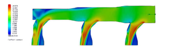
Behavior of different sized particles in cyclone has been investigated through CFD and DEM combined method. 64 Pa pressure drop value that has been found with calculation, found 57 Pa with simulation method. (Example simulation results can be found below.)

Keywords: Cyclone Calculation, Cyclone Simulation, Engineering, Calculation
*All the calculations, codings, files, tables and writings in this page are information only. We can not be held responsible for any inconvenience might occur using these.

Venturimeter Calculation
It is a measuring instrument used to measure the flow rate of fluids, in the form of a thin tube, open at both ends, and narrowing at both ends towards the middle. While the fluid velocity reaches its highest value in the narrowest cross-sectional part of the tube, which becomes thinner and forms the throat, the fluid pressure decreases and a pressure difference occurs between the wide-sectioned part of the tube and the narrow-sectioned part. This pressure difference is measured with the help of a "Closed manometer" connected to the inlet and outlet of the venturimeter. The flow rate of the fluid passing through the tube is determined with the help of the pressure values obtained as a result of this measurement.
Parameter
A1 (Area)
Value
A2 (Area)
Air Density
P1
P2

Unit
m²
m²
kg/m³
Pa
Pa
Volumetric Flow Rate (m³/h)=
##
You can download detailed document about Venturimeters below.
Keywords: Venturimeter, Flow Rate Measurement, Flow Rate Calculation.
*All the calculations, codings, files, tables and writings in this page are information only. We can not be held responsible for any inconvenience might occur using these.
Perforated Metal Sheet Open Area
Kullanımı kolay birim dönüştürücü ile uzunluk, kütle, sıcaklık, hız ve daha fazlasını anında çevirin. Hızlı ve doğru hesaplamalar için hemen deneyin!
Easily convert length, mass, temperature, speed, and more with our user-friendly unit converter. Try it now for fast and accurate calculations!
Round Perforation - 60 Degree Staggered

Hole Size (mm)

Pitch (mm)
##
Round Perforation - 45 Degree Staggered

Hole Size (mm)
Pitch (mm)

##
Round Perforation - Straight Line


Hole Size (mm)
Pitch-1 (mm)
Pitch-2 (mm)
##
Square Perforation - Straight Line


Square Hole Edge Length (mm)
Pitch-1 (mm)
Pitch-2 (mm)
##
Square Perforation - Staggered


Hole Width (mm)
Pitch-1 (mm)
Pitch-2 (mm)
##
Hex Perforation


Hole Size (mm)
Pitch (mm)
##
Round - End Slot - Side Staggered

Hole Width (mm)
Hole Length (mm)
Pitch-1 (mm)
Pitch-2 (mm)
##
Round - End Slot - Straight Line

Hole Width (mm)
Hole Length (mm)
Pitch-1 (mm)
Pitch-2 (mm)
##
Square - End Slot - Straight


Hole Width (mm)
Hole Length (mm)
Pitch-1 (mm)
Pitch-2 (mm)
##
Square - End Slot - Staggered

Hole Width (mm)
Hole Length (mm)
Pitch-1 (mm)
Pitch-2 (mm)
##
unit converter, unit conversion, online unit converter, measurement unit conversion, conversion tool, unit calculation, online calculator, engineering calculations, physical units, technical converter, metric conversion, imperial conversion, SI units conversion, US units conversion, length conversion, distance conversion, meter conversion, km conversion, mile conversion, inch conversion, ft conversion, mass conversion, weight conversion, kg conversion, gram conversion, pound conversion, ounce conversion, ton conversion, temperature conversion, Celsius conversion, Fahrenheit conversion, Kelvin conversion, Rankine conversion, area conversion, square meter conversion, sq ft conversion, dönüm conversion, hectare conversion, acre conversion, volume conversion, capacity conversion, cubic meter conversion, liter conversion, gallon conversion, cubic ft conversion, speed conversion, m/s conversion, km/h conversion, mph conversion, knot conversion, fps conversion, angle conversion, degree conversion, radian conversion, gradian conversion, frequency conversion, Hertz conversion, kHz conversion, MHz conversion, GHz conversion, RPM conversion, data storage conversion, byte conversion, bit conversion, kB conversion, MB conversion, GB conversion, TB conversion, pressure conversion, Pascal conversion, kPa conversion, bar conversion, psi conversion, atm conversion, mmHg conversion, Torr conversion, energy conversion, work conversion, Joule conversion, kJ conversion, kWh conversion, calorie conversion, BTU conversion, eV conversion, power conversion, Watt conversion, kW conversion, horsepower conversion, HP conversion, BTU/h conversion, density conversion, kg/m³ conversion, g/cm³ conversion, lb/ft³ conversion, lb/gal conversion, force conversion, Newton conversion, kN conversion, kgf conversion, lbf conversion, mass flow rate conversion, kg/s conversion, kg/h conversion, lb/h conversion, flow rate conversion, thermal conductivity conversion, heat conductivity conversion, W/mK conversion, heat transfer coefficient conversion, heat transfer coefficient conversion, W/m²K conversion, online calculation
unit converter, conversion tool, convert units, online unit converter, measurement converter, calculator, length conversion, mass conversion, temperature conversion, speed conversion, area conversion, volume conversion, pressure conversion, energy conversion, power conversion, metric conversion, imperial conversion, SI units, meters to feet converter, kg to pounds converter, celsius to fahrenheit converter, engineering units, online calculation
Unit Converter

Length

Weight

Time

Temperature

Area

Volume

Speed

Angle

Frequency

Data

Pressure

Energy

Power

Density

Force

Mass Flow

Thermal Cond.
Meter
Meter
Kilometer |
Meter |
Decimeter |
Centimeter |
Millimeter |
Micrometer |
Nanometer |
Mile |
Yard |
Foot |
Inch |
Nautical Mile |
Kilometer |
Meter |
Decimeter |
Centimeter |
Millimeter |
Micrometer |
Nanometer |
Mile |
Yard |
Foot |
Inch |
Nautical Mile |
unit converter, unit conversion, online unit converter, measurement unit conversion, conversion tool, unit calculation, online calculator, engineering calculations, physical units, technical converter, metric conversion, imperial conversion, SI units conversion, US units conversion, length conversion, distance conversion, meter conversion, km conversion, mile conversion, inch conversion, ft conversion, mass conversion, weight conversion, kg conversion, gram conversion, pound conversion, ounce conversion, ton conversion, temperature conversion, Celsius conversion, Fahrenheit conversion, Kelvin conversion, Rankine conversion, area conversion, square meter conversion, sq ft conversion, dönüm conversion, hectare conversion, acre conversion, volume conversion, capacity conversion, cubic meter conversion, liter conversion, gallon conversion, cubic ft conversion, speed conversion, m/s conversion, km/h conversion, mph conversion, knot conversion, fps conversion, angle conversion, degree conversion, radian conversion, gradian conversion, frequency conversion, Hertz conversion, kHz conversion, MHz conversion, GHz conversion, RPM conversion, data storage conversion, byte conversion, bit conversion, kB conversion, MB conversion, GB conversion, TB conversion, pressure conversion, Pascal conversion, kPa conversion, bar conversion, psi conversion, atm conversion, mmHg conversion, Torr conversion, energy conversion, work conversion, Joule conversion, kJ conversion, kWh conversion, calorie conversion, BTU conversion, eV conversion, power conversion, Watt conversion, kW conversion, horsepower conversion, HP conversion, BTU/h conversion, density conversion, kg/m³ conversion, g/cm³ conversion, lb/ft³ conversion, lb/gal conversion, force conversion, Newton conversion, kN conversion, kgf conversion, lbf conversion, mass flow rate conversion, kg/s conversion, kg/h conversion, lb/h conversion, flow rate conversion, thermal conductivity conversion, heat conductivity conversion, W/mK conversion, heat transfer coefficient conversion, heat transfer coefficient conversion, W/m²K conversion, online calculation
SHEET METAL DESIGN CRITERIA
Minimum Sheet Metal Bend Length
✅ Why 3T + R?
-
The distance required for the material to be bent without deformation:
-
If a flange is made too close to the bend line, deformation, cracking at the edge of the sheet, or die damage may occur.
-
This rule is used both to ensure manufacturability and to extend tool life.
-
-
Spreading (stretching) effect in the bend area:
-
During bending, the material compresses on the inner side and stretches on the outer side.
-
To balance this effect, a certain minimum flat flange (3T) and bend radius (R) are required.
-

Minimum Hole Diameter
❌Why is D < T not recommended?
-
Increased risk of die damage:
If the hole diameter is too small, the punch used during punching can break or wear out quickly. -
Decreased hole quality:
In the D < T condition, the resulting part may be burred, deformed, or cracked. The edge of the sheet metal cannot be cut cleanly. -
Material deformation:
Small diameter holes can lead to fracture without yielding (or before entering the plastic region), especially in high-strength steels.

Minimum Distance of Hole from Bend
❓ Why is this recommendation made?
1. To prevent metal deformation:
During bending, the material stretches and elongates. If the hole is too close to the bend line, it will deform or become elliptical.
2. To prevent crack formation:
Since the area around the hole is under stress, holes placed too close become susceptible to cracking.
3. To reduce manufacturing errors:
In processes performed with laser cutting, punching, or bending dies, burrs, edge tearing, or distortion can occur if the minimum distance is not adhered to.
4. Assembly precision:
If this tolerance is not adhered to, the hole axis will shift after bending, leading to bolt/hole alignment problems.
If high precision is required >4T+R

Center to Center Distance Between Two Holes
❓ Why is this recommendation made?
-
Material around the hole may become insufficient:
If the holes are too close, the sheet metal in between will tear, crack or deform.
-
Deformation occurs during the punching process:
When the sheet metal piece in between becomes too thin, the punch can not cut the material cleanly, which can lead to burrs, hole deviation, or tool damage.
-
Stress concentration is prevented:
In operations such as bending, welding, or screw assembly, if there is not enough distance between holes, stresses will combine and can lead to tearing.

Extrude Hole Size & Position Guidelines
❓ Why are these recommendations made?
-
Extruded holes require high force:
The drawing process performed with a punch+die combination applies very high local force. This leads to a risk of tearing if too close to the edge.
-
The drawn hole puts a load on the surrounding material:
If placed too close to the sheet edge, bend area, or other holes, insufficient yielding distance remains, and the material "breaks" or goes out of form.
-
Turnability and threadability are affected:
For example, if a threaded hole (like M4-M6) is to be drawn, circumferential support is required for this geometry, depending on the sheet metal thickness. Insufficient support = thread stripping or seizing.

Sheet metal design rules, Sheet metal bending standards, Minimum bend radius sheet metal, Sheet metal hole punching guidelines, Sheet metal tolerances, Sheet metal fabrication guide, Hole to edge distance sheet metal, Extruded hole design sheet metal, Punch tool life, Sheet metal engineering, Design for manufacturability (DFM) sheet metal, Stress concentration sheet metal, Metal sheet design tips, Material deformation in sheet metal bending, Minimum flange length sheet metal.


Pressure vessels are indispensable equipment in industrial facilities, used for the safe storage and transportation of gases or liquids under high pressure. The design of these vessels requires not only engineering knowledge but also a thorough understanding of regulations and standards. The EN 13445 standard, widely used in Europe, and the ASME Boiler and Pressure Vessel Code (BPVC), originating from America, exhibit significant differences in terms of design criteria, material selection, manufacturing processes, and testing methods. This guide addresses a wide audience, from students to designers new to the industry and experienced engineers, explaining fundamental concepts in clear language while also providing a comparative presentation of the EN and ASME standards.
Basic Standards and Approaches
EN 13445-3:2009: European pressure vessel standard, used for CE conformity.
-
Sheet thickness calculations, safety factors, and weld coefficients are defined.
-
It allows both formula-based and analysis-based calculations for stress analysis (DBF, DBA).
ASME VIII Div.1-2-5: American standard, widely used internationally.
-
Safety factors are higher (Div.1), and it requires more detailed analysis (Div.2-5).


Volume Calculation
Volume of a cylindrical
pressure vessel:
V = π . r² . h + Vdome
V: Volume (m³),
r : Internal Radius (m),
h : Cylindrical Shell Length (m),
Vdome : Dome Volume (m³)
Hemispherical Dome Volume Calculation:
Volume of a hemispherical dome:
V = 2/3. π . r³
V: Volume (m³),
r : Dome Internal Radius (m).
Elliptical Dome Volume Calculation:
Volume of a elliptical dome:
V = 0,25. π . D² . h
V: Volume (m³),
D : Dome Internal Diameter (m),
h : Internal height of dome cover (m).
CALCULATION OF SHEET THICKNESS (DBF)
Acc. to EN13445:
e: Minimum Wall Thickness (mm),
P : Design Pressure (MPa),
Dᵢ : Internal Diameter (mm),
z : Weld coefficient
e =
P . Dᵢ
2.f.z - P
Acc. to ASME Div.1:
t: Wall Thickness (mm),
P : Internal Pressure (MPa),
R : Internal Radius (mm),
S : Allowable Material Stress (MPa)
E : Weld coefficient
t =
P . R
S.E - 0,6 . P
HEAD DEPTH and STRESS DISTRIBUTION
The shape of pressure vessel heads (end caps) directly affects the distribution of stress that occurs under internal pressure. If the head geometry is not chosen appropriately, high stress concentrations can occur, especially in the head-shell transition zones. This situation can lead to cracking, tearing, or fatigue problems in the long term.
One of the most fundamental ratios used in this context is as follows:
β =
h
D
In the Formula;
β = Dome height ratio (Dimensionless),
h = Internal height of dome cover (mm),
D = Dome Internal Diameter (mm).
-
The type of dome determines the stress distribution.
-
The most suitable stress distribution occurs in the hemispherical dome, but manufacturing is difficult.
-
Elliptical dome is economical and stress distribution is balanced.
What is the meaning of β ?


📉What does EN 13445 Figure 7.5-1 & 7.7-1 show?


In these graphs, the corresponding β ratios for different types of domes are:
-
Stress concentration coefficients (k),
-
Minimum dome height recommendations,
-
Geometric limits for weak points on the dome wall,
visually presented, allowing the designer to easily predict the stress distribution to be expected at any dome height.
Sample Application Formula:
e =
4 . f . k - 0,2 . P
P . D


Here:
-
e: Minimum wall thickness (mm)
-
P: Internal Pressure (MPa)
-
D: Dome diameter (mm)
-
f: Allowable strength of the material (MPa)
-
k: Coefficient determined from graphs according to β value
What should the designer do?
-
The type of dome is selected (elliptical, torispheric, hemispherical, etc.)
-
The diameter and height of the dome are designed → β is calculated
-
The appropriate k value is taken from the EN 13445 graphics.
-
With this "k" value, the sheet thickness "e" is calculated.
-
If necessary, verification is done with FEM analysis.
This method helps ensure both safe and economical design.
Nozzle Placement and Reinforcement
Reinforcement plates are required in areas where nozzles will be opened:
-
EN 13445 charts are used (Section 9).
-
The increase in stress in the nozzle area must be verified by FEM.
Supports and Supporting Structures
-
Saddle supports are used in horizontal vessels.
-
Skirt or leg type supports are applied in vertical tanks.
-
Load on the legs: self-weight + test fluid + earthquake effect
Earthquake and Static Loads
-
Earthquake loads must be included in accordance with clause 5.3.1 of EN 13445-3.
-
Earthquake effect = mass × acceleration
Fatigue and Design Life
-
For cases exceeding 500 full pressure cycles, fatigue analysis according to Clause 17-18 is mandatory.
-
Calculations can be performed up to 106 cycles for safe design.
Corrosion Allowance (C)
-
Typical: 1-3 mm
-
C = 0 can be accepted in non-corrosive environments.
Material Selection
-
Standard materials within EN 13445-2 or ASME II-D should be preferred.
-
In material selection, both mechanical strength, and weldability, toughness, and corrosion resistance must be considered.
-
Strength values (yield and tensile strength) must be taken according to the design temperature at which they are used.
Example Materials:


📌 Note: The values above are approximate and may differ based on the heat treatment and test temperature specified in the material certificates.
-
If the design temperature increases (e.g., 150–300 °C), the yield strength of the material decreases.
-
EN and ASME tables provide separate f or S values for each temperature range. These values are directly inserted into the formula.
Recommendation:
-
Carbon steels (e.g., P265GH) → economical and weldable but susceptible to corrosion.
-
Stainless steels (e.g., SA-240 304) → expensive but have high chemical resistance.
-
If it will operate in a corrosive environment, protective coating or anodic protection should also be considered after material selection.
Safety Factors According to Standards


Sources
-
EN 13445-3:2009 Document
-
ASME BPVC 2023 (Div.1-2)
-
PED 2014/68/EU for CE conformity
This page guides design decisions, not just calculations. All information and calculations presented here are for informational purposes only and do not constitute any engineering liability.
If you need a detailed and standard-compliant pressure vessel design, I offer a comprehensive service covering the entire process from project initiation to CE certification. You can contact me if you need professional support in design, engineering calculations, analysis (FEM/CFD), project management, technical drawing preparation, and process consultancy.
🔧 I am with you with experience, confidence, and design compliant with regulations.


pressure vessel design, EN 13445 calculations, ASME Section VIII design, head shape stress distribution, pressure vessel wall thickness, nozzle reinforcement calculation, FEM analysis pressure vessel, CE compliant pressure equipment, static analysis of pressure tank, elliptical and hemispherical head design, mechanical design consultancy, pressure vessel engineering services, industrial equipment CAD modeling, SolidWorks pressure vessel design, corrosion allowance in vessel design, fatigue analysis in pressure vessels, pressure vessel project management, PED 2014/68/EU compliant design
Perforated Metal Sheet Open Area
Endüstriyel egzoz, toz toplama veya çoklu hava dağıtım sistemleriniz için; hava hızını sabit tutarak ana hat ve branşman (çıkış/giriş) çaplarını otomatik hesaplayın.
Tek bir kaynaktan gelen havayı, birden fazla çıkışa belirli oranlarda bölmek mi istiyorsunuz? Bu araç, hattan debi eksildikçe sistemdeki akış hızını koruyacak şekilde ana kanal çapının nasıl daraltılması gerektiğini hesaplar. Özel prosesler, kurutma fırınları veya malzeme taşıma hatları için idealdir.
Toz, talaş veya ağır partikül emişi yapan sistemlerde, malzemenin boru dibine çökmemesi için taşıma hızının asla düşmemesi gerekir. Bu araç, fana doğru ilerlerken farklı noktalardan emilen debiler birleştikçe, akış hızını sabit tutacak şekilde kanal çapını kademeli olarak büyütür.